Using RTX to Accelerate Instant Radiosity
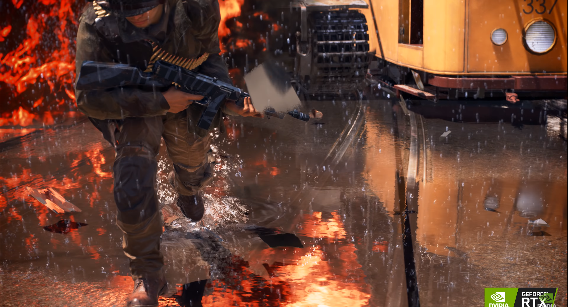
The past 2018 was an exciting year for computer graphics. Nvidia announced RTX graphics cards which brings real-time ray tracing to consumers. Following the announcement, we saw new releases of mainstream game series including Battlefield V and Shadow of the Tomb Raider, putting RTX powered graphics in their games. This screenshot below captured from a Battlefield V promotion video (https://www.youtube.com/watch?v=rpUm0N4Hsd8) shows super clear ray traced reflections in water.
 .
.
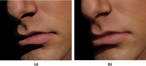
However, the recent new game releases branded with RTX graphics mostly use RTX for tracing reflections and shadows (including soft shadow), many other possibilities with real-time ray tracing are still to be explored. Of course, ray traced reflections and shadows can largely enhance the overall graphics quality, considering the importance of these two components and how bad their quality was even using very complex rasterization tricks. But there are still tons of possible applications of real-time ray tracing that can lift the overall graphics quality to a new level. For example, we can achieve more faithful subsurface scattering in translucent objects like marbles and human skin. Current technique use shadow maps to estimate the distanced traveled by light inside the object, which can fall short with concave objects and have artefacts around object edges. But ray tracing simply avoids all artefacts brought by rasterization tricks and everything will appear as they should be.
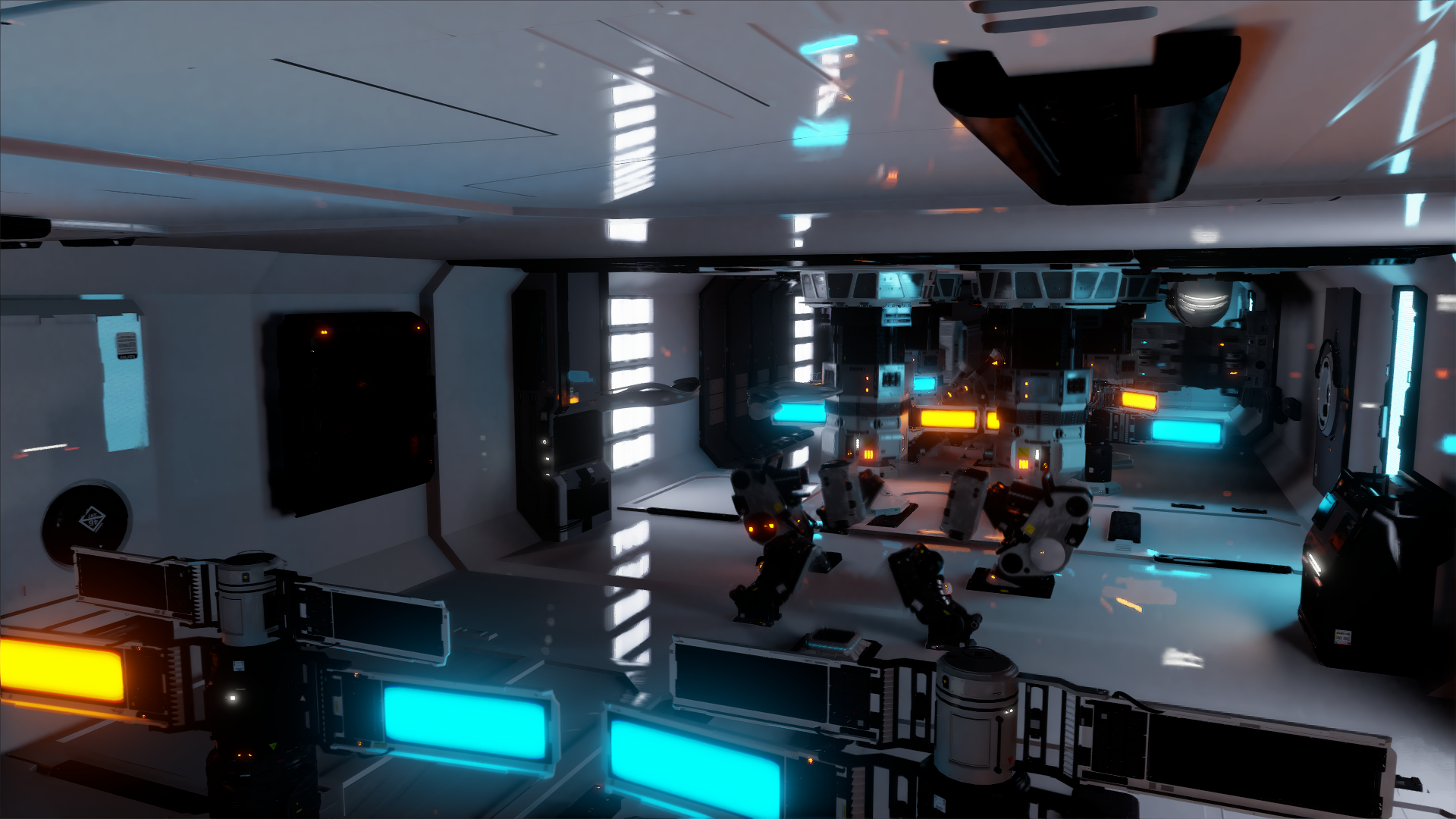
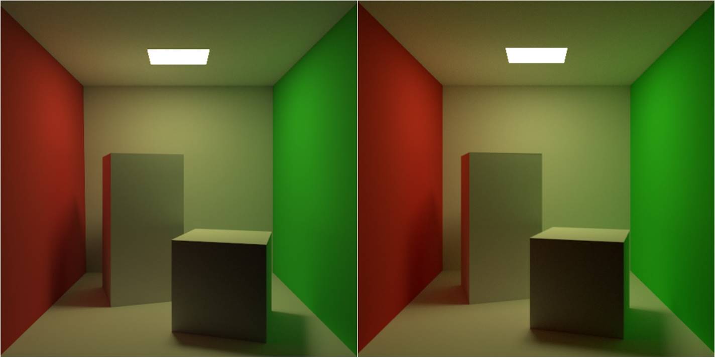
The thing I want to advocate is using RTX to generate virtual point lights (VPL) and trace shadow rays to them. This technique is known as instant radiosity, introduced by Alexander Keller in 1997. It resembles bidirectional path tracing and photon mapping in the sense that it also traces light paths and records hit positions along the paths. These surface records are then used as point lights that represent discretized indirect lighting. Comparing to photon mapping, instant radiosity is cheap and effective to render smooth diffuse reflection, thanks to the low frequency spatial radiance distribution of point lights. A few hundreds of VPLs are enough to provide indirect lighting from a small light source with reasonable quality (of course, there is singularity problem caused by the point light approximation, but that can be bypassed by setting a minimum distance between point lights and surface points), which often requires more than 1M photons when using photon mapping to eliminate the wavy artefact. As a result, virtual point lights have been used in games for flashlights. An example is the rendering of indirect illumination in rooms from gun mounted flashlights in Gears of War 4. [Malmros, 2017] (talk: https://www.youtube.com/watch?v=c0VxzGRIUCs) The developers used reflection shadow maps [Dachsbacher & Stamminger, 2005] (http://www.klayge.org/material/3_12/GI/rsm.pdf) to sample single-bounce VPLs and merge VPLs according to some geometric and material heuristics to lower the computational cost. This technique gives real-time single bounce GI (likely unshadowed). The following screenshots from the talk video a comparison between flashlight aiming at the red tapestry and the wall. Clearly, the technique generates reasonable color bleeding as shown by the change of color on the ceiling.
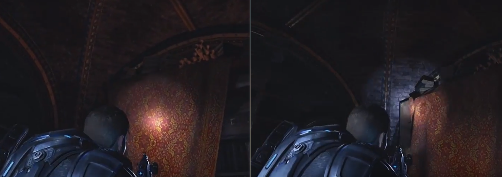
Looking carefully into the talk video, there are some temporal incoherence as the flashlight moves. However it is not obvious in a dark environment like this, especially when using a moving FPS game character. But the render quality can still be improved if the virtual point lights can be generated and evaluated at a lower cost. First, using more VPLs improves the temporal stability and reduces the bright blotches. Also, given strict performance requirements Gears of War 4 probably only used didn’t trace shadow rays to VPLs for indirect illumination shadows, which could be very important given a more complex scene setting. Now with RTX available, we can make VPLs much cheaper, solving the aforementioned problems.
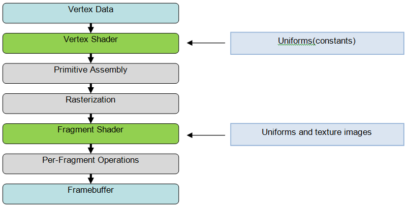
DirectX Ray Tracing
There are several options to get access to the ray tracing function in RTX cards. But the most convenient one for PC gaming development is the DirectX Ray Tracing (DXR) API, which integrates seamlessly with the rasterization pipeline we use everyday. There is a very nice introduction to DXR from Nvidia (https://devblogs.nvidia.com/introduction-nvidia-rtx-directx-ray-tracing/). In most concise words, DXR breaks the ray tracing process into three new shaders, “raygen”, “hit” and “miss”. Rendering starts from “raygen” or ray generation, invoked in a grid manner like a compute shasder. In all shaders, calling TraceRay() executes the fixed function hardware scene traversal using an acceleration structure (BVH). Because can a ray can hit any object, a shader table is used to store shading resources for each geometry object. Upon intersection, the entry for the current object can be retrieved from the shader table to determine which shaders and textures to use. With these functions, we can virtually implement all possible ray tracing functions with DXR, except choosing and our own acceleration structure (for example, k-d tree).
Example Implementation
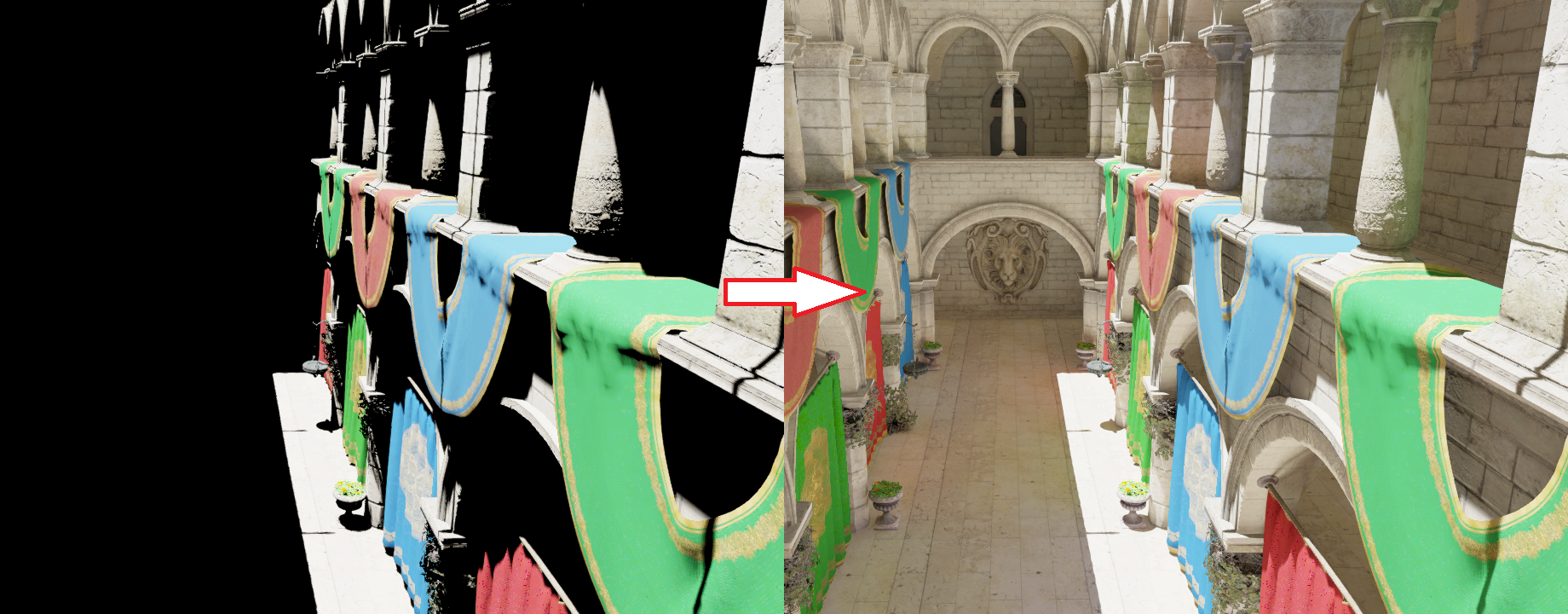
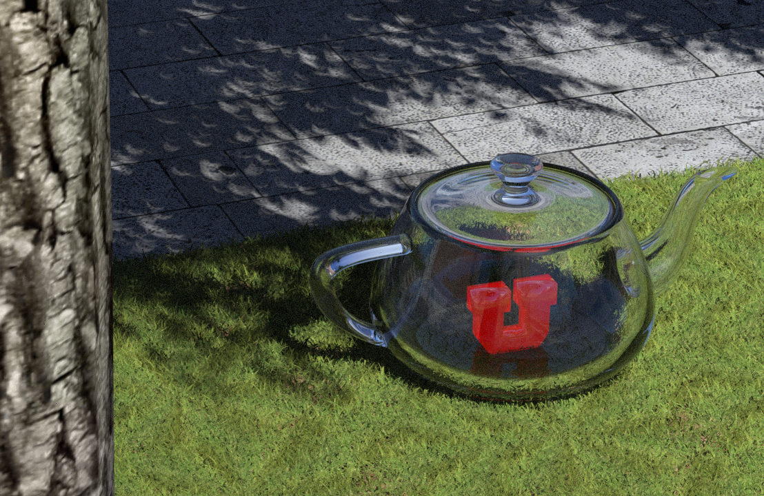
Here I provide a brief code walk through of using DXR to implement the original (brute force) instant radiosity algorithm. Some parts of code is modified from the Microsoft MiniEngine DXR example (https://github.com/Microsoft/DirectX-Graphics-Samples). Notice that it is not meant to be interactive as the original instant radiosity is an offline rendering algorithm that goes through all virtual point lights for each pixel, and shooting shadow rays to resolve the visibility. In our experiment we will generate 1 million VPLs for at most two-bounce indirect diffuse reflection and render a 1280x720 instant radiosity image. This means we need to trace 921.6 giga shadow rays against the scene. My DXR program running on an RTX 2080 takes 25 minutes to render a instant radiosity image for Crytek Sponza (262k triangles), about 600 mega rays per second which is quite impressive. Please notice that I a very unoptimzed way of tracing shadow rays (trace shadow rays for one light for all pixels in each frame with which contains a fixed G-buffer overhead). With proper optimization, the speed should at least reach 1 Giga rays per second. The VPL generation process is relatively fast, taking less than 2 ms. Here is the raygen shader I used to generate the VPLs.
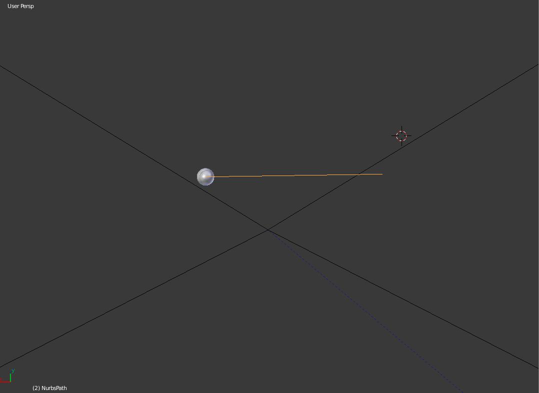
To sample light rays from a directional distant light (sun light), I used a function like this to randomly sample a point from the top disk of the bounding cylinder of the scene bounding sphere aligned to the sun light direction (a technique introduced in PBRT). This point is then used as the origin of the light ray, which is then traced through the scene and make diffuse bounces when intersecting with surfaces.
void GenerateRayFromDirectionalLight(uint2 seed, out float3 origin, out float pdf)
{
	float3 v1, v2;
	CoordinateSystem(SunDirection, v1, v2); // get a local coordinate system
	float2 cd = GetUnitDiskSample(seed + DispatchOffset);
	float3 pDisk = SceneSphere.xyz - SceneSphere.w * SunDirection +
            SceneSphere.w * (cd.x * v1 + cd.y * v2);
	origin = pDisk;
	pdf = 1 / (PI * SceneSphere.w * SceneSphere.w);
}
DXR requires us to specify the ray using a ray description (RayDesc) structure that contains the origin, tMin (min parametric intersection distance along the ray), ray direction and tMax. Additionally, for this algorithm we also need to define a payload structure that records the carried radiance on the light path which I call “alpha”. It is multiplied with the surface albedo and the cosine factor during each surface hit. The payload also stores the current recursion depth. This payload feeds the last argument of TraceRay, which can pass the information from ray generation to hit shader and between bounces.
/// some resource and function definitions
    ...

struct RayPayload
{
	float3 alpha;
	uint recursionDepth;
};

[shader("raygeneration")]
void RayGen()
{
	float3 origin;
	float pdf;
        // using the 2D ray dispatch index as random seed
	GenerateRayFromDirectionalLight(DispatchRaysIndex().xy, origin, pdf);
	float3 alpha = SunIntensity / pdf;

	RayDesc rayDesc = { origin,
		0.0f,
		SunDirection,
		FLT_MAX };
	RayPayload rayPayload;
	rayPayload.alpha = alpha;
	rayPayload.recursionDepth = 0;

        // defition of parameters can be found on
        //   https://developer.nvidia.com/rtx/raytracing/dxr/DX12-Raytracing-tutorial-Part-2

	TraceRay(accelerationStructure, RAY_FLAG_NONE, ~0, 0, 1, 0, rayDesc, rayPayload);
}
Here is the “closesthit” shader that creates VPLs at surface hits. I use three DX12 linear buffers (StructuredBuffer) to store VPL positions, normals and colors (flux). An atomic counter is incremented and returned each time a new VPL is created to prevent writing to the same position. Following that, a diffuse reflection ray is sampled from the hemisphere centered at the surface normal to generate next bounce. Notice how DXR provides a wide range of fixed functions and variables that stores necessary ray tracing information we need for lighting computation. For example, barycentric coordinates are fetched from “BuiltInTriangleIntersectionAttributes” and the intersection distance is provided in RayTCurrent().
/// some resource and function definitions
    ...

[shader("closesthit")]
void Hit(inout RayPayload rayPayload, in BuiltInTriangleIntersectionAttributes attr)
{
	uint materialID = MaterialID;
	uint triangleID = PrimitiveIndex();
	RayTraceMeshInfo info = meshInfo[materialID];

        ///fetch texture coordinates (uv0, uv1, uv2), vNormal), vBinormal, vTangent for triangle vertices
        ...

	float3 bary = float3(1.0 - attr.barycentrics.x - attr.barycentrics.y, attr.barycentrics.x, attr.barycentrics.y);
	float2 uv = bary.x * uv0 + bary.y * uv1 + bary.z * uv2;

	float3 worldPosition = WorldRayOrigin() + WorldRayDirection() * RayTCurrent();
	uint2 threadID = DispatchRaysIndex().xy + DispatchOffset;
	const float3 rayDir = normalize(-WorldRayDirection());
	uint materialInstanceId = info.m_materialInstanceId;
	const float3 diffuseColor = g_localTexture.Sample(defaultSampler, uv).rgb;
	float3 normal = g_localNormal.SampleLevel(defaultSampler, uv, 0).rgb * 2.0 - 1.0;
	float3x3 tbn = float3x3(vTangent, vBinormal, vNormal);
	normal = normalize(mul(normal, tbn));

        // sample a diffuse bounce
	float3 R = GetHemisphereSampleCosineWeighted(threadID * (rayPayload.recursionDepth+1), normal);
	float3 alpha = rayPayload.alpha;

        // attenuate carried radiance
	alpha *= diffuseColor;

        // increment atomic counter
	uint VPLid = g_vplPositions.IncrementCounter();

        // store a new vpl
	g_vplPositions[VPLid] = worldPosition;
	g_vplNormals[VPLid] = normal;
	g_vplColors[VPLid] = alpha;

        //push to vpl storage buffer
	if (rayPayload.recursionDepth < MAX_RAY_RECURSION_DEPTH)
	{
		TraceNextRay(worldPosition + epsilon * R, R, alpha, rayPayload.recursionDepth);
	}
}
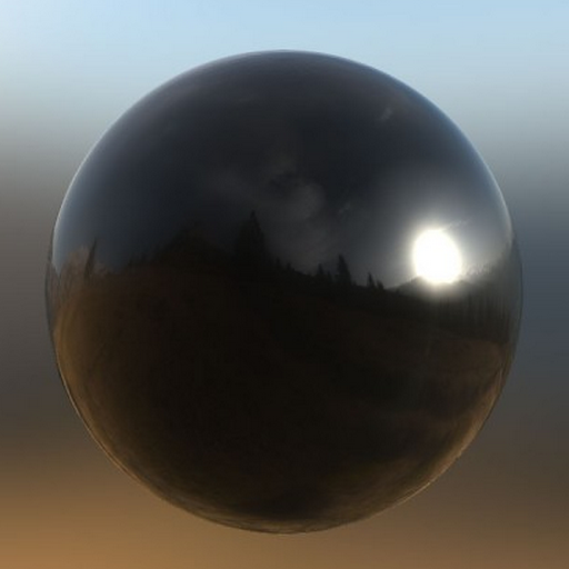
Finally, we can gather the VPL contribution for all visible pixels to generate an irradiance buffer. Notice that texPosition and texNormal are surface world position and normal from the G buffer.
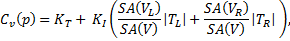
The irradiance $E$ can be calcuated as $ E = \Phi \frac{<n_s, r><n_l, -r>}{||r||^2} $, where $\Phi$ is VPL flux, $n_s$, $n_l$ are surface normal and VPL normal, $p_s$, $p_l$ are surface and VPL positions, and $r$ is the normalized shadow ray direction.
The following shader code shows computing the contribution from one VPL, indexed by VPLId. A shadow ray is traced to resolve the visibility between current pixel and VPL, and the max ray T is set to the light distance which means any hit is an occlusion. This message can be stored in the ray payload as a boolean. Because we are tracing shadow rays, it is better to set RAY_FLAG_ACCEPT_FIRST_HIT_AND_END_SEARCH argument in TraceRay() to avoid the unnecessary search of closest hit.
/// some resource and function definitions
    ...

/// an anyhit shader setting payload.IsOccluded to translucent
    ...

[shader("raygeneration")]
void RayGen()
{
	float3 output = 0;

	int2 screenPos = DispatchRaysIndex().xy;

	float3 SurfacePosition = texPosition[screenPos].xyz;
	float3 lightPosition = vplPositions[VPLId].xyz;
	float3 lightDir = lightPosition - SurfacePosition;
	float lightDist = length(lightDir);
	lightDir = lightDir / lightDist; //normalize

	// cast shadow ray
	RayDesc rayDesc = { SurfacePosition,
			  0.1f, //bias
			  lightDir,
			  lightDist };

	ShadowRayPayload payload;
	payload.IsOccluded = false;

	TraceRay(g_accel, RAY_FLAG_ACCEPT_FIRST_HIT_AND_END_SEARCH,
		~0, 0, 1, 0, rayDesc, payload);
	if (!payload.IsOccluded) // no occlusion
	{
		float3 SurfaceNormal = texNormal[pixelPos].xyz;

		float3 lightNormal = vplNormals[VPLId].xyz;
		float3 lightColor = vplColors[VPLId].xyz;

		output = max(dot(SurfaceNormal, lightDir), 0.0) * lightColor;
		output *= max(dot(lightNormal, -lightDir), 0.0) / (lightDist*lightDist + CLAMPING_BIAS);
	}

	irradianceBuffer[pixelPos] += output / numVPLs;
}
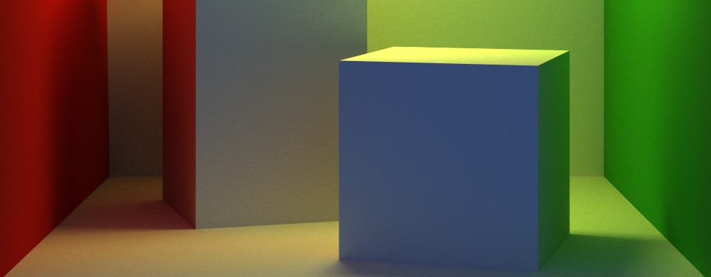
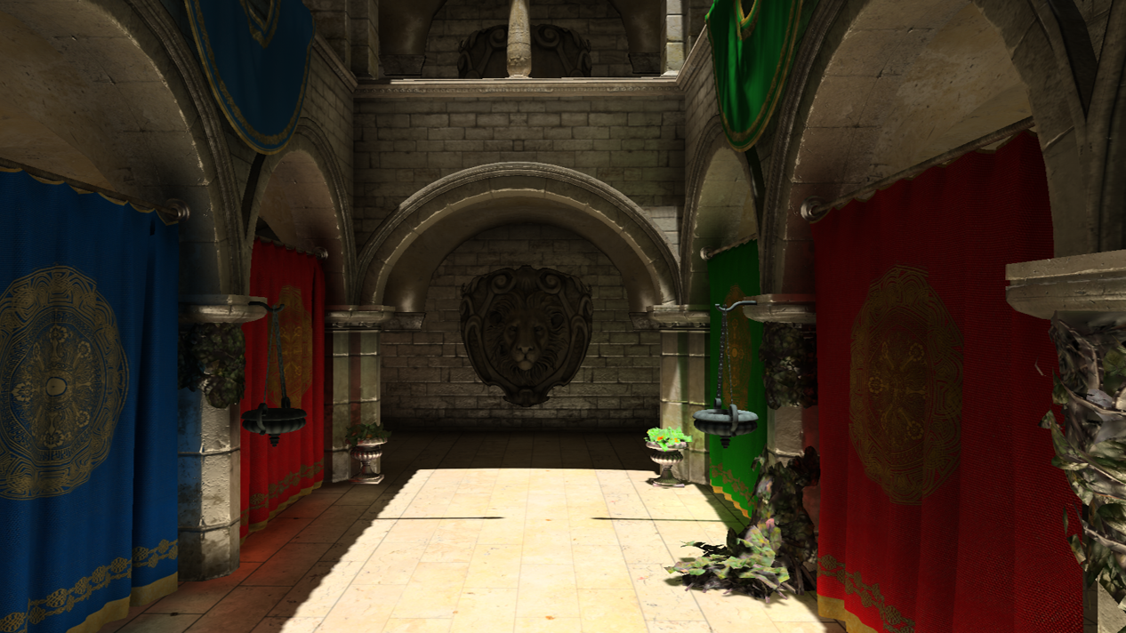
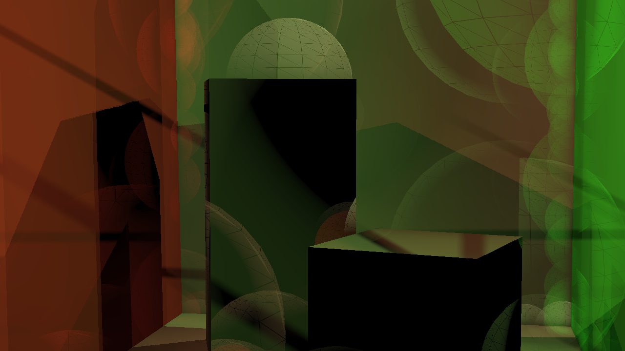
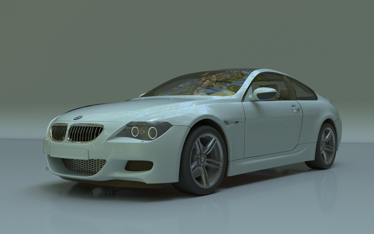
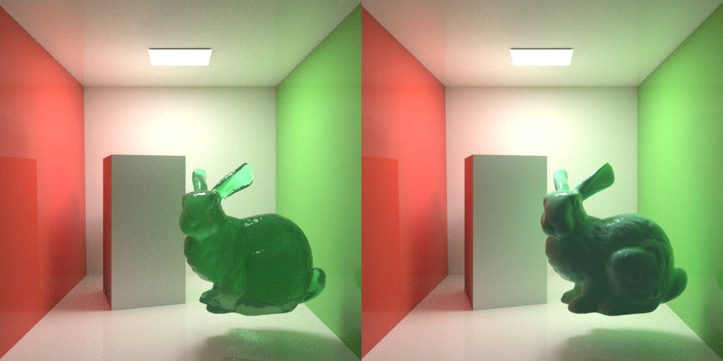
After we iterate through all VPLs, we can modulate the irradiance buffer with the surface albedo to produce the final indirect illumination and add that to the direct illumination. And here is the final image.
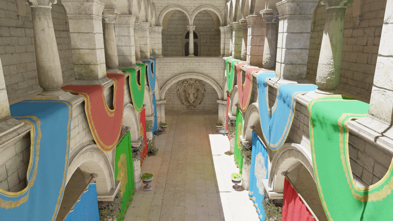 .
.
If you look into VPL-based GI literature, you’ll find a ton of methods that approximates the instant radiosity with a dramatic reduction in evaluation cost. But none of them can reach real time performance yet. But we’ll continue with this topic to see what RTX can bring us for real time global illumination.
References
Dachsbacher, C., & Stamminger, M. (2005, April). Reflective shadow maps. In Proceedings of the 2005 symposium on Interactive 3D graphics and games (pp. 203-231). ACM.
Malmros, J. (2017, July). Gears of War 4: custom high-end graphics features and performance techniques. In ACM SIGGRAPH 2017 Talks (p. 13). ACM.
...
Stencil Buffer Trick for Volume Deferred Shading
Deferred shading have been known to largely boost the efficiency of rendering when treating a large amount of lights. The mechanism is very simple: separate the geometry complexity from lighting. To do this, G-buffers which form an array of textures, often including position, material color, normal of the points to shade, are rendered in the first pass from the point of view. Then, an orthographic camera are used to render a quad that covers the whole screen. The normalized (0-1) screen coordinates are then used to retrieved the geometry/material data at the point of the screen, which is fed into the lighting function. In such a way, we avoid producing tons of fragments from the projected scene geometry, instead, only render those which are visible.
However, imagine we have a large group of lights. We’ll still have to go through the whole list of lights for each screen pixel. With a more physically based lighting model, in which each light has a influential radius (resulted from the physical fact that has an ideal point light source has inverse squared drop-off), fragments that are outside a certain light’s influential radius would waste time on waiting other fragments in the same batch to go to a different branch. We know that branching is bad for GPU. This leads to a severe time penalty. Many techniques have been proposed to alleviate this problem. Tiled deferred shading is a very popular method, probably most of you have heard of. It partition the screen into tiles and create a “light list” for each tile using only the lights that intersect with the tiles. This is of course an elegant method. However, we will always need to do some preprocessing before generating a new group of lights (if there is a need to).
A simpler solution is volume deferred shading. We just need to render “light volumes” for each light, which, as you might guess, can be a sphere with a radius equal to the light’s influential radius. For example, in OpenGL, we just need to create a list of vertices/indices of a sphere and prepare a model matrix for each light (which is simply scaling and translation). While rendering, we perform the draw call n times, where n is the number of lights. One such light volume will produce fragments that covers the specific region on the screen where the fragments are possible to be shaded by the light. Of course, by doing this we are losing the depth dimension. We have to explicitly test the fragments and make sure they are at about the same depth region of the light (which is only a necessary condition). Of course, tile rendering also require such testing, but if we have lights scattering everywhere in a very “deep” scene, the lights to be tested are significantly lesser. However, because no preprocessing are required, volume deferred shading have quite competitive performance in most cases.
Wait! We should not render n passes! Instead, a better way is to use the instancing function which is supported on every modern graphics card to avoid the latency caused by lots of communication between CPU and GPU. Also another important thing, depth write should be disabled and additive blending should be enabled. The reason that depth write should be disabled is that light volumes are not real geometry. While two light volumes are close to each other and are illuminating the same region of the scene, we don’t want them to occlude each other such that some part are only shaded by one of the light volumes.
If you do the volume deferred shading described above directly, we will immediately discover that something goes wrong. When you approaches a light’s location (with a moving camera), at some point the screen will suddenly be darkened. This is because no matter you turn backface culling on/off, you will fall in a dilemma that you either render the pixels twice as bright when you are out of the light volume, or not render anything when you are inside the light volume.
It turns out that this situation can be easily solved by switching the culling mode to front-face culling. However, this is not good enough. We can actually keep the Z buffer created by G-buffers rendering and use this information perform some rejection of fragments that are not intersected by light volumes. Here is a nice stencil buffer trick introduced by Yuriy O’Donnell (2009). What it do is basically using the stencil buffer as a counter to record whether the front face of a light volume is behind the visible scene geometry (so that it has no chance to shade the pixel). This is achieved by only rendering front faces (with color buffer write disabled) in the first pass and add 1 to the stencil of the Z-failed pixels. Another situation is that the backface of a light volume is before the visible scene geometry, which is solved by the second pass - rendering only back faces and use a Greater/Equal z-test to continue filter the final pixels from the pixels with a zero stencil value (already pass the first test). So that we can keep only the light volume pixels that “fail” the z-test (the original “LESS” one), which intuitively corresponds to the scene geometry-generated pixels that intersects with the light volume. Notice this trick also works when you are inside a light volume, in which case front faces won’t get rendered (it is illogical that the fact that we are inside a light volume and that the front face is behind the visible geometry hold at the same time!), leaving a zero stencil value that allow us to use Greater/Equal depth test only to filter the pixels to be shaded. Of course, in either pass we need to disable Z write. Certainly we don’t want the light volumes bumping into each other.
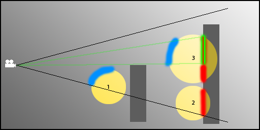
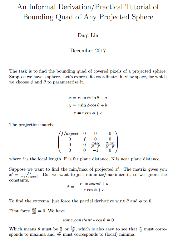
While this trick definitely increases the efficiency especially when the lighting situation is very complex, we can do something better. Often modeling a detailed sphere as polygon creates large number of vertices that cram up the pipeline. Instead, we can use a very coarse polygon-sphere (e.g., with 4 vertical/horizontal slices) with a slightly larger radius to ensure that the light volume is bounded correctly. We can even use just a bounding cube of the light volume! Of course, the least thing we can do is just use a quad. However, that gives up some aforementioned depth test benefits and it also involves some complex projective geometry. Just for fun, I also prepared a derivation of the axis-aligned screen space bounding quad of the projected sphere.
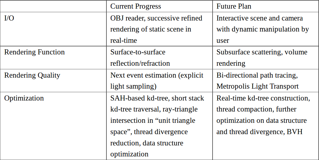
[GAPT Series - 5] Current Progress & Research Plan
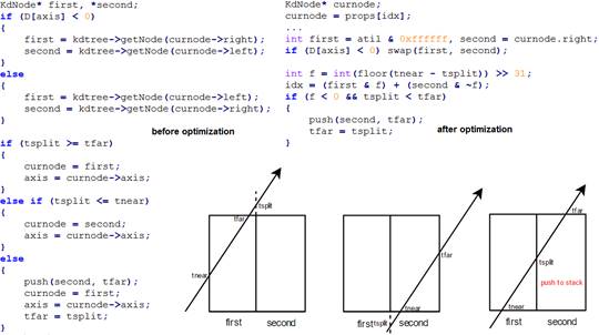
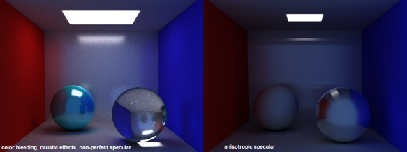
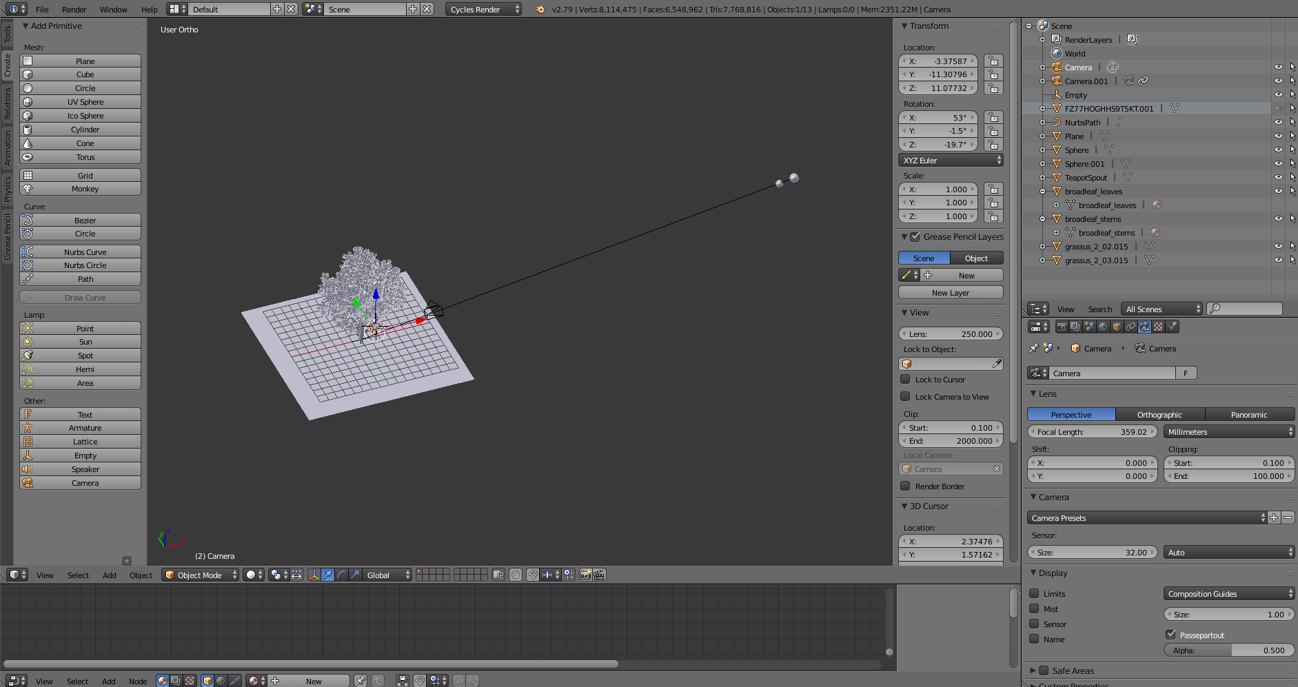
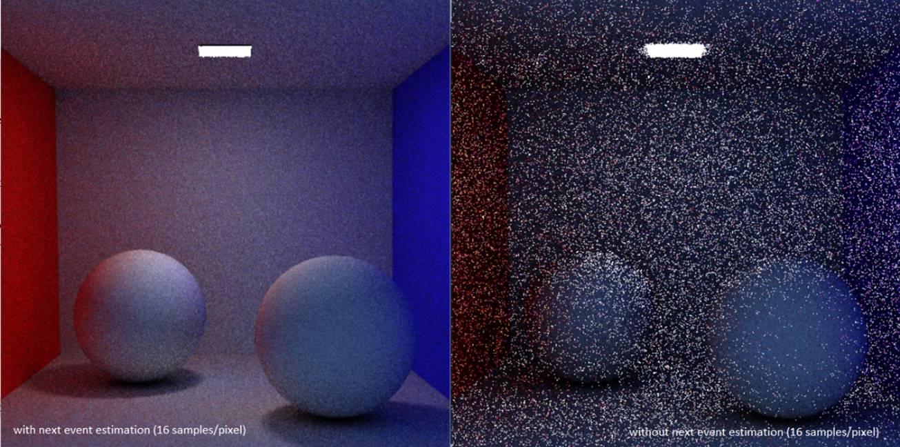
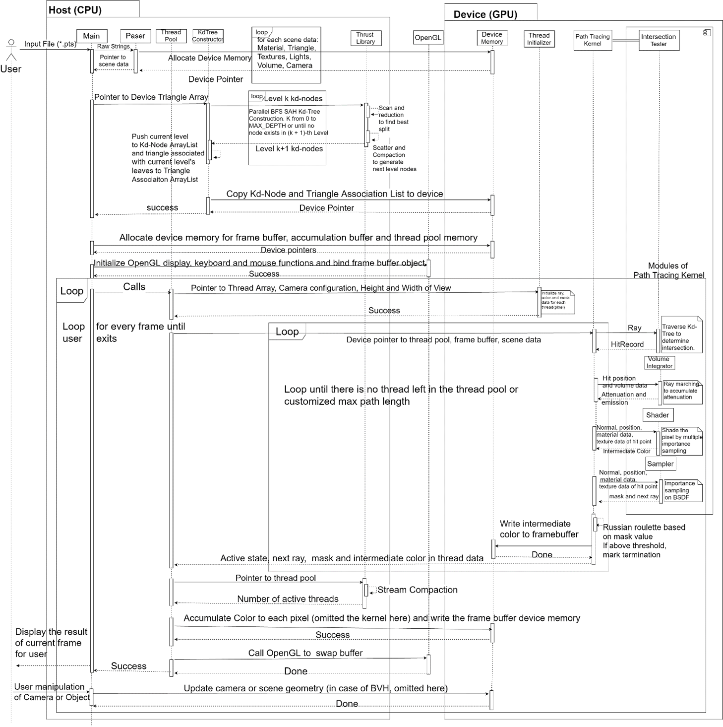
Currently, I have implemented a Monte Carlo path tracer (demo) with full range of surface-to-surface lighting effects including specular reflection on anisotropic material simulated by GGX-based Ward model. A scene definition text file is read from the user, whose format is modified from the popular Wavefront OBJ format by adding material description and camera parameters. I use triangle as the only primitive due to simplicity and generality. Integrated with OpenGL and using a successive refinement method, the path tracer can display the rendering result in real time. Optimization methods include algorithm-based methods: SAH based kd-tree, short stack kd-tree traversal, ray-triangle intersection in “unit triangle space”, next event estimation (explicit light sampling); and hardware-based methods: adoption of GPU-friendly data structure which has a more coalesced memory access and better cache use, reduction of thread divergence which boosts warp efficiency, etc.
...