2.1 The Concept
Image Based Lighting is basically treating all pixels in an image as light sources. Usually, an environment map (usually cubemap) created from a panoramic, high dynamic range (HDR) image will be used as the source of texture fetch. Assuming the shaded object to be opaque, we only need to consider specular reflection and diffuse reflection. However, since the light source is numerous continuous pixels, we need to integrate BRDF to get the shading result of a surface point. In computer graphics, integration is approximated by sampling. To achieve more accuracy, the number of samples is proportional to the number of pixels, which is a large number in real-time rendering. Therefore, a method is baking necessary steps into texture and fetching the pixel in real-time rendering. Before that, we need to solve a problem – how to fetch a pixel from environment map?
2.2 Fetching Pixels from Environment Map
On any kind of surface, the radiance value of a pixel can be seen as reflected from the other side of the surface normal (this is actually the case for specular reflection on perfectly smooth surface, but for other situation like diffuse reflection, the environment map can store an imaginary source point as the composite result of radiance), having the same angle with normal as the view direction. In other words, the pixel we need to fetch can be seen as the target that the camera ray hit after reflection.
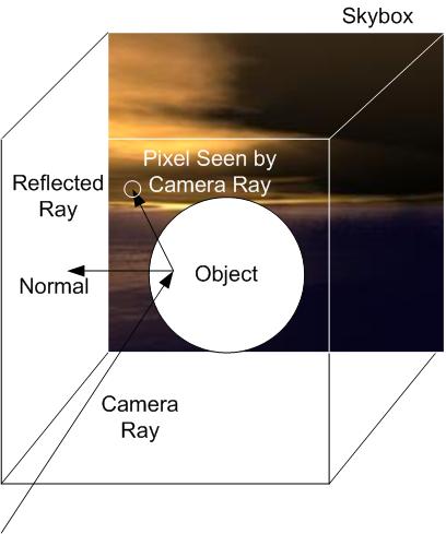
Cube mapping is a popular method of environment mapping as it has simple mathematical form. This method treat environment as a surrounding box with the environment panorama wrapped and mapped into 6 faces. In GLSL, there is a function textureCube() to do the fetch in a given reflecting direction. However, the reflected ray is assumed to be at the exact center of the cube. This is not a severe issue for skyboxes that represents faraway environment. However, when we need to represent reflection inside a small room, the reflection is heavily distorted if we want to fetch the reflected color for a ball close to a wall.
To solve the problem, I found a method called box projected cubemap environment mapping (BPCEM) (behc, 2010).
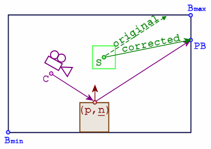
This method has a simple mathematical form. As the Figure 4 shows, it requires the size of the room and the relative position of the shaded object. The position of the intersection between the borders and the reflected camera ray will then be calculated easily. The corrected fetching direction is then the vector between the assumed sampling center (center of the room by default) and the intersection. This method is very intuitive and has very good approximation result. Therefore, I adapted the method in GLSL for rendering inside closed rooms as scene.
2.3 Irradiance Map and Spherical Harmonics
After solving the texture fetching problem, we come back to calculate illumination in IBL. The diffuse part of IBL is particularly non-trivial. The texture we want to pre-calculate according to BRDF is known as irradiance map. Unlike specular reflection which only has a small range of sampling which increases with the surface roughness according to Cook-Torrance model, the IBL diffuse reflection need to consider contributions from pixels in all visiable directions, which is a vast amount comparing with specular reflection. Real-time sampling is nearly impossible and even preprocessing becomes hard. Thanks to SIGGRAPH, there is a efficient approximation to the calculation of irradiance map (Ravi & Pat, 2001). It turns out that by computing and using 9 spherical harmonic coefficients of the lighting, the average error of rendering result is only 1%.
I wrote a C++ program to compute the 9 spherical harmonic coefficient for any cubemap under the size of 2048x2048 almost instantly. With the 9 spherical harmonic coefficients, the irradiance value of a given pixel can actually be computed in real-time. However, to avoid long expressions in shader, I pre-compute the result as irradiance map by a traversal of all reflecting directions.
2.4 Efficient Approximation of Specular Reflection
The Cook-Torrance microfacet specular shading model (Cook&Torrance, 1981) is used to calcualte the IBL specular reflection.
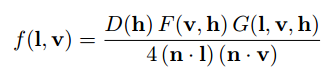
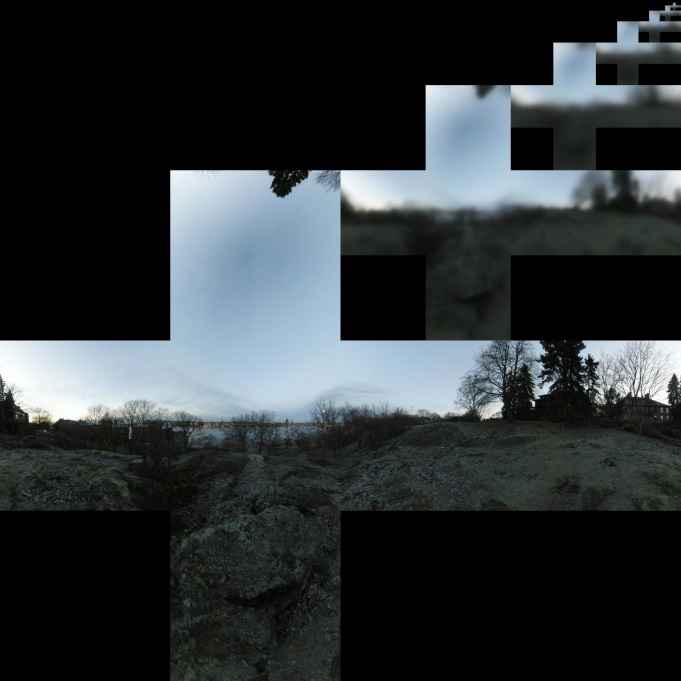
The D, F and G stands for Beckmann distribution factor, Fresnel term and geometric attenuation term respectively. However, the 3 formulas are also complex and efficient approximation need to be found. Thanks to SIGGRAPH again, a real shading model in Unreal Engine 4 was presented in SIGGRAPH 2013 course (Karis, 2013), in which computationally efficient algorithms were chosen to approximate the formulas and the integration. The integration was done by importance sampling, a general technique for approximating properties of a specific distribution. To further reduce scale of computation, a method called Split Sum Approximation was raised in this essay. The integration is split into the product of two sums, both of which can be pre-calculated. The first sum is a convolution of environment map as a result of given roughness under Cook-Torrance microfacet model. Because we want to choose different level of roughness for different objects in the same environment, there is a need to store result for different roughness value in mip-map levels of a cubemap. There is a DirectX image format called DirectDraw Surface (.dds) that supports storage of self-created mip-map levels. Unfortunately, Blender does not support reading mip-maps in this format. Therefore, I come up with a method that arranges all cubemap mip-map levels in a normal bitmap texture (as shown in Figure 5) and fetches the desired pixel in corresponding region.
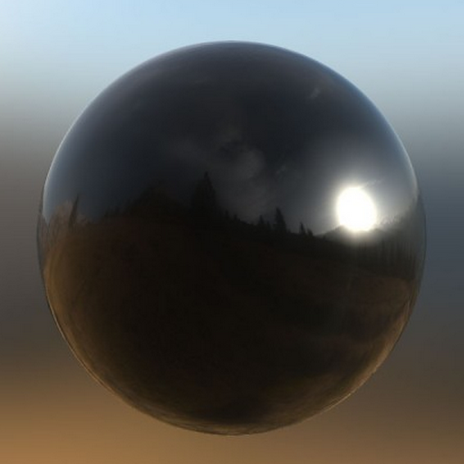
The second sum, equivalent with integrating specular BRDF with a pure white environment, is easier to compute. It can be further approximate to the sum of another two integrals and leaves roughness and incident angle as two inputs, giving a scale and a bias as two outputs. Furthermore, all parameters fall into the range between 0 and 1; therefore, the result of the function can be pre-calculated and stored in a texture. It is noticeable that the second sum contains Fresnel term. Fresnel term, a factor that describes how reflectivity changes with different incident angles, exhibits stronger contrast between center and edge when the shaded object has lower metalness (the base reflectivity of non-metal is lower and the reflectivity of all material approaches 100% when the reflecting angle gets closer to 90 degrees). Since this effect is empirically easy to notice, it is indispensable for the realistic rendering.
2.5 The IBL Tool
Doing physically based rendering is not an easy process. Physical entities has continuous geometry, while the calculation in computer science is on a discrete basis. Calculus used in physics like integral must be converted to the form of discrete sampling. Even that, the current computational power still requires many approximation techniques and procedural tactics like look-up texture (LUT). The IBL is a very good example to demonstrate the complexity of PBR. Because of that, a tool that does all the pre-computations with minimal input commands would be convenient for artists and programmers to use. Therefore, I developed IBL Tool, a windows console program to make things easy (Sorry, this IBL Tool is now a proprietary software of my intern company so I cannot release it :). User only need to put the environment map texture inside and all LUT textures for IBL are produced. The program also exhibits customizability. User can choose from 3 different kind of output pattern – the separated faces, the standard Blender format and spread box format, as how the game engine requires.
In addition, a pair of sample GLSL shaders (vertex and fragment) is also provided with the program with custom fields indicated. A tone mapping that adjusts exposure and Gamma value is also included, so that user can get higher dynamic range for shading if required.
References
Behc (2010, April 20) Box Projected Cubemap Environment Mapping [Online forum post]. Retrieved from http://www.gamedev.net/topic/568829-box-projected-cubemap-environment-mapping/.
Cook, R. L., & Torrance, K. E. (1981, August). A reflectance model for computer graphics. In ACM Siggraph Computer Graphics (Vol. 15, No. 3, pp. 307-316). ACM.
Karis, B., & Games, E. (2013). Real Shading in Unreal Engine 4. part of “Physically Based Shading in Theory and Practice,” SIGGRAPH.
Ramamoorthi, R., & Hanrahan, P. (2001, August). An efficient representation for irradiance environment maps. In Proceedings of the 28th annual conference on Computer graphics and interactive techniques (pp. 497-500). ACM.
List of Figures
Figure 3: Cubemap Pixel Fetching Illustration. Source: https://en.wikipedia.org/wiki/Reflection_mapping
Figure 4: Box Projected Cubemap Environment Mapping. Source: behc’s post on http://www.gamedev.net/topic/568829-box-projected-cubemap-environment-mapping/
Figure 5: Cook-Torrance Specular Shading Model. Source : Karis’ notes at SIGGRAH 2013 on http://blog.selfshadow.com/publications/s2013-shading-course/karis/s2013_pbs_epic_notes_v2.pdf
Figure 6: Storing Cubemap Mip-map Levels in a Single Texture. Source: My original picture generated by OpenCV.
Figure 7: Fresnel Effect on a Dielectric Ball. Source : an article “Interaction of Light and Materials” on http://www.pernroth.nu/lightandmaterials/